How to Select the Right Pipeline Isolation Plug for High-Pressure Natural Gas Lines: A Field Engineer’s Checklist

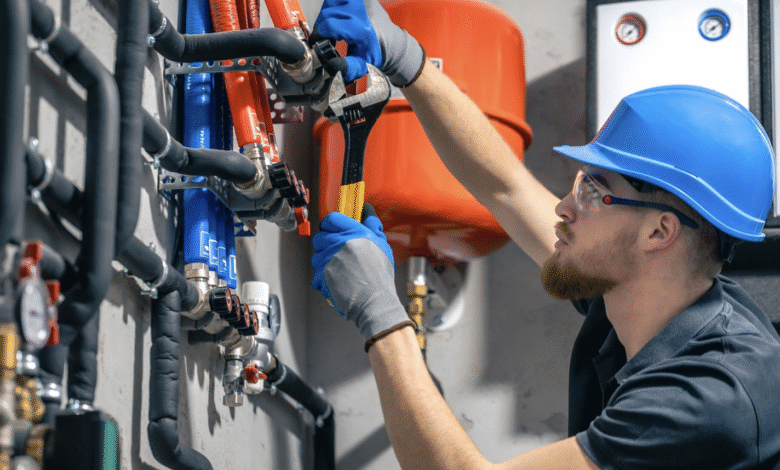
Maintenance work on high-pressure natural gas lines rarely happens in controlled, predictable conditions. Crew schedules shift, isolation windows are tight, and the margin for equipment failure is effectively zero. When a section of pipe needs to be taken offline for inspection, repair, or valve replacement, the method used to isolate that segment carries significant weight. Choose the wrong approach, and the consequences range from extended downtime to life-safety incidents. Choose correctly, and the work proceeds on schedule with the system protected throughout.
The problem most field engineers encounter is not a shortage of options — it is an absence of structured criteria for evaluating those options against the specific demands of their line. Pressure ratings, pipe geometry, gas composition, and access limitations all affect which isolation method is appropriate. This checklist is intended to work through those criteria methodically, so that selection decisions are made on operational grounds rather than habit or availability.
Understanding What a Pipeline Isolation Plug Is and Why Selection Matters
A pipeline isolation plug is a mechanical device inserted into a pipe to create a temporary, pressure-rated barrier that allows work to take place safely downstream or upstream of the plug location. Unlike a valve-based shutoff, an isolation plug is placed directly inside the pipe, either through a fitting or by bypassing the existing valve infrastructure. This distinction matters because the plug itself becomes the primary pressure boundary during the work window. It is not a backup measure — it is the control point.
When evaluating options for any given job, engineers should treat the selection of a pipeline isolation plug with the same rigor applied to any pressure-containing component on the system. A device that is rated for a lower pressure class, or that is not designed for gas service specifically, introduces risk that the work plan may not account for. The variability in plug types — inflatable, mechanical, cup-type, bypass-equipped — reflects genuine differences in application requirements, not just product differentiation.
The American Petroleum Institute’s guidelines on pipeline maintenance and pressure control, particularly those referenced under API pipeline safety standards, reinforce that temporary isolation equipment must be treated as a critical barrier device with appropriate documentation and inspection protocols before any live-line work begins.
The Difference Between Isolation and Depressurization
One of the more common errors in isolation planning is treating a pressure reduction as equivalent to full isolation. Reducing operating pressure in a gas line lowers the risk profile, but it does not eliminate it. A plug inserted into a partially pressurized line still needs to be rated for the residual pressure present at the time of insertion and for any pressure that could build up if upstream conditions change during the work window. This is particularly relevant on transmission lines where pressure fluctuations can occur quickly and without warning from a control room perspective. The plug must be selected to handle a dynamic pressure environment, not just a static snapshot of the line at the moment work begins.
Gas Service vs. Liquid Service Ratings
Plugs rated for liquid pipelines are not automatically appropriate for gas lines. Gas is compressible, which means a failure in the isolation barrier releases stored energy differently than a liquid leak would. The expansion behavior of natural gas under pressure creates a hazard profile that demands isolation equipment specifically tested and certified for gas service. When reviewing manufacturer documentation, engineers should verify that the device carries gas-service certification, not just a general pressure rating. This is a straightforward verification step that is sometimes skipped when equipment is sourced under time pressure.
Evaluating Pipe Geometry and Access Conditions
The internal geometry of the pipe being isolated determines which plug types are physically compatible with the installation. Pipe diameter, wall thickness, internal coating condition, and the presence of bends, fittings, or weld seams near the intended plug location all influence whether a given device will seat properly and hold under load. An isolation device that fits well in a straight, clean-bore section may not perform the same way in a line with mill scale buildup, internal corrosion, or surface irregularities near the seating zone.
Working with Existing Valve Infrastructure
In many natural gas distribution and transmission systems, isolation plugs are deployed through existing valve bodies or through hot-tap fittings installed specifically for the purpose. The compatibility between the plug and the fitting through which it will be launched is not a trivial concern. Thread type, bore diameter, and pressure rating of the access fitting must be confirmed before equipment is mobilized to the site. Discovering a mismatch at the job site creates delays and, in some cases, requires work to be suspended until compatible equipment is sourced. A pre-job compatibility check that includes fitting documentation prevents this scenario reliably.
Accounting for Flow During Installation
Not all isolation jobs take place on a static, offline segment. In some cases, the plug must be installed into a line that is flowing, with flow then redirected or stopped after the plug is in place. This requires a device designed for insertion under flow conditions, with features that prevent the plug from being displaced or improperly seated by the gas stream during installation. The selection process should confirm whether the job requires a live-insertion-rated device and, if so, whether the equipment being considered carries that specific certification. Using a standard plug in a flow condition it was not designed for is one of the more preventable sources of isolation failure in field operations.
Pressure Rating, Temperature Range, and Environmental Conditions
The operating conditions of a natural gas line at the time of isolation are not always identical to the system’s normal operating parameters. Pressure may be temporarily elevated due to supply demand, or reduced due to a controlled drawdown ahead of the job. Temperature at the pipe wall varies with burial depth, ambient conditions, and the thermal effects of gas flow rates. Any isolation plug used in the operation must be rated to perform across the actual range of conditions present during the work window, not just the nominal operating conditions documented in the system records.
Seal Material Compatibility
The sealing element of a pipeline isolation plug — whether an inflatable bladder, a mechanical cup, or a compression gasket — must be chemically compatible with natural gas and any additives or odorants present in the line. Some elastomers degrade when exposed to specific gas compositions or odorant concentrations, which reduces the integrity of the seal over time or under load. Material data sheets for the sealing element should be reviewed against the known composition of the gas being isolated. This step is particularly important on older distribution systems where odorant formulations may differ from what newer equipment is tested against.
Low-Temperature Considerations for Buried or High-Altitude Lines
In cold climates or at elevation, the pipe wall temperature during a maintenance window can fall significantly below ambient air temperature, particularly if gas flow has been stopped ahead of the isolation. Many sealing materials lose flexibility at low temperatures, which affects their ability to conform to the pipe wall and maintain a consistent seal. Engineers working in cold-weather environments should confirm the low-temperature operating limit of the plug’s sealing components and compare that limit against the expected pipe temperature at the time of use. This is one area where equipment that performs well in temperate conditions may not be suitable for northern or high-altitude installations without modification.
Bypass Requirements and Pressure Equalization Before Removal
Once the maintenance work is complete, removing an isolation plug from a pressurized line requires that the pressure differential across the plug be equalized before the device is extracted. Attempting to remove a plug against unequalized pressure is dangerous and can result in sudden ejection of the device or uncontrolled gas release. Many pipeline isolation plug designs include an integrated bypass port specifically for this equalization step, allowing pressure to be restored gradually across the plug before removal begins. When selecting a plug for high-pressure gas service, the presence and capacity of the bypass feature should be treated as a functional requirement, not an optional upgrade.
Monitoring Isolation Integrity During the Work Window
A properly selected and installed plug should hold its rated pressure for the duration of the work window, but field conditions are not always stable. Temperature changes, pressure fluctuations upstream, and mechanical disturbances from nearby work activity can all affect isolation integrity. Best practice on high-pressure gas jobs includes continuous or periodic pressure monitoring on the isolated segment throughout the work window. This allows the crew to detect any loss of plug integrity before it becomes a safety incident and to take corrective action before the work area is compromised.
A Practical Pre-Job Checklist for Plug Selection
Before finalizing equipment selection for any high-pressure natural gas isolation, field engineers should confirm the following points as a minimum standard:
• The plug carries a gas-service certification specific to the pressure class of the line being isolated, not just a general pressure rating from liquid-service testing.
• The sealing element material has been confirmed as compatible with the gas composition and any odorants present in the line.
• The device is rated for the full temperature range expected at the pipe wall during the isolation window, including low-temperature conditions for buried or cold-climate installations.
• Physical compatibility between the plug and the access fitting has been verified using actual fitting documentation, not assumed from nominal size alone.
• If installation will occur under flow conditions, the plug carries a live-insertion rating appropriate for the flow rate and pressure present at insertion.
• The plug includes an integrated bypass port or an approved external bypass method for pressure equalization prior to removal.
• A pressure monitoring plan is in place for the duration of the work window, with defined response procedures if isolation integrity is lost.
• All documentation for the isolation device — certifications, inspection records, and prior use history — has been reviewed and is available on site for the work crew.
Closing Considerations
Selecting a pipeline isolation plug for high-pressure natural gas service is a decision that carries real operational and safety consequences. The range of available equipment is wide, and the differences between options are not always obvious from product descriptions alone. What distinguishes a sound selection from a risky one is the degree to which the chosen device has been evaluated against the actual conditions of the job — not generic industry conditions, not the system’s normal operating parameters, but the specific pressure, temperature, geometry, gas composition, and access conditions that will exist during the isolation window.
The checklist framework in this article is not exhaustive, but it covers the categories of evaluation that most commonly surface in post-incident reviews when isolation equipment fails. Working through each category systematically before equipment is committed to a job reduces the likelihood of discovering incompatibilities on site, and it creates a documented basis for the selection decision that supports both safety compliance and operational accountability.
The best isolation plans are built before the crew arrives, not improvised around what equipment is available in the truck. Treating plug selection as a deliberate engineering decision — with defined criteria, documented verification, and appropriate review — reflects the standard that high-pressure gas work genuinely demands.