Why DFM Should Be Completed Before Injection Mold Manufacturing
A CAD model can look complete and still be unready for tooling. Wall thickness, gate position, ejection, resin shrinkage, or assembly problems may only become obvious after T1, when changes are slower and more expensive.
An injection molding DFM review should therefore be completed before mold design approval and steel cutting. Its purpose is to identify risks, compare practical options, and record what the customer and manufacturer have agreed to before tooling begins.
DFM Is a Tooling Decision
Design for manufacturing in injection molding reviews the part, resin, expected volume, mold concept, appearance, assembly, and quality requirements together.
It is not an automatic software check or a guarantee that T1 will be perfect. It also does not mean every supplier suggestion must be accepted. A design can remain unchanged when the risk is understood, documented, and accepted by the project team.
Mold flow analysis may support complex or high-risk parts, but it is not necessary for every project. The level of analysis should match the geometry, material, tolerances, and production risk.
Start With the Correct Project Information
A DFM review is only useful when it is based on the current design and real production requirements. An outdated CAD file or unclear material assumption can make an otherwise detailed report irrelevant.
| Input | Why it matters | Risk if missing |
| Latest 3D model | Defines the current geometry | The wrong design may be reviewed |
| Controlled 2D drawing | Defines tolerances, datums, and notes | Approval requirements remain unclear |
| Material or performance target | Affects shrinkage, flow, and release | Advice may not suit the resin |
| Expected volume | Influences cavities, cooling, and mold life | The mold may be overbuilt or underbuilt |
| Cosmetic zones | Guides gates, parting lines, and ejection | Marks may appear on visible surfaces |
| Assembly requirements | Connects molding with final function | A moldable part may still fail in assembly |
When the resin has not been selected, the input can describe temperature, impact, chemical exposure, stiffness, or other performance needs. The report should then state which material assumptions were used.
What Should an Injection Molding DFM Review Check?
The review should focus on whether the part can fill, cool, release, assemble, and be inspected with reasonable consistency. Generic design rules are not enough on their own.
Part Geometry and Moldability
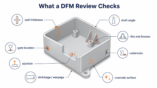
The main checks include wall thickness, thick-to-thin transitions, ribs, bosses, radii, draft, undercuts, deep features, threads, and snap fits.
Local thick areas may cool slowly and cause sink marks or warpage. Insufficient draft can lead to sticking, scratches, or ejector damage.
There is no single wall thickness or draft angle that works for every part. Resin grade, feature depth, surface texture, flow length, and product function all affect the recommendation.
Tooling and Production Risk
The report should also consider parting direction, gate location, weld lines, ejector positions, slides, lifters, venting, cooling access, and material shrinkage.
For multi-cavity molds, filling balance and cavity variation may also need attention. A feature that works in a single-cavity prototype mold may be more difficult to control across several cavities.
This stage does not replace detailed mold design. It confirms that the part geometry leaves room for a practical mold concept.
Material and Volume Change the Answer
The same part may require different changes when molded in ABS, POM, TPU, or glass-filled nylon. These materials behave differently during filling, cooling, shrinkage, release, and long-term use.
A thick screw boss in an ABS enclosure, for example, may create a different surface and dimensional risk in a glass-filled nylon structural part. The response could involve changing the boss connection, wall transition, gate location, or inspection method.
Production volume matters as well. A low-volume validation mold does not need the same cooling system, wear components, or maintenance plan as a multi-cavity mold expected to run for several years.
A DFM Report Should Record Decisions
A DFM report for injection molding should do more than label features as “OK” or “NG.” It should show where the risk is, why it matters, and what action is required.
| Report item | What it should show |
| CAD and drawing revision | Exact files used for the review |
| Marked risk location | Highlighted feature, section, or screenshot |
| Reason for concern | Molding, tooling, appearance, or assembly impact |
| Recommended option | A practical design or tooling response |
| Risk if unchanged | Likely result during tooling or production |
| Status and owner | Open, revised, accepted, or closed |
The report should separate required changes from optional improvements. It should also record when the original design is retained despite a known risk.
This turns the report into an approval record rather than a collection of screenshots.
DFM Is Not Mold Design or Validation
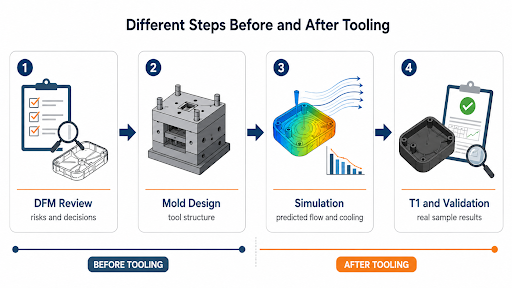
DFM, mold design, simulation, and trial molding are connected, but they answer different questions.
| Activity | Main purpose | Output |
| DFM review | Identify part and production risks | Decisions and recommended changes |
| Mold design | Define how the tool will form and release the part | Mold layout and construction drawings |
| Mold flow analysis | Predict filling, packing, shrinkage, or cooling | Simulation results |
| T1 and validation | Check the real mold and molded parts | Samples, measurements, and corrections |
Completing DFM reduces avoidable problems. It does not replace mold trials, dimensional inspection, assembly testing, or production validation.
Review Appearance and Assembly Together
A part can fill correctly and still be unacceptable. On a visible enclosure, gate marks, ejector marks, parting lines, texture transitions, and draft must be reviewed against the approved cosmetic zones.
Assembly creates additional constraints. Screw bosses must suit the selected fastener. Snap fits need room to engage and release. Connector openings require controlled datums, while sealing surfaces may be affected by parting lines or distortion.
In consumer electronics injection molding, these requirements often overlap. Housing appearance, connector alignment, bosses, snap fits, sealing features, EMI needs, and final assembly may all depend on the same areas of the part.
The inspection method should also be agreed early. Some dimensions may need to be measured after conditioning or in the assembled state rather than immediately after molding.
Use a Clear DFM Approval Process
A practical process can be kept to five stages:
- Confirm the inputs. Check the current 3D model, drawing, resin, volume, appearance, assembly, and quality requirements.
- Review the part risks. Examine walls, draft, undercuts, critical features, material behavior, and production needs.
- Develop the initial mold direction. Review parting, gates, ejection, side actions, and major tool complexity.
- Issue and resolve the report. Record risks, options, decisions, owners, and approval status.
- Approve the direction before cutting steel. Freeze the design revision, material assumptions, and validation scope.
The first step is not checking draft angle. It is confirming that the engineering team is reviewing the correct product revision.
What Should Be Approved Before Tooling?
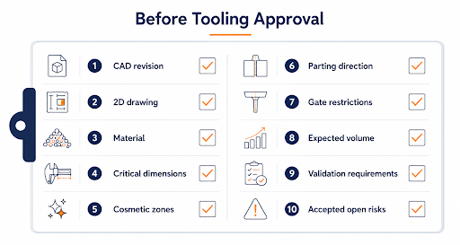
Before mold design is released, the project team should confirm:
- Current CAD and drawing revision
- Final or provisional material
- Critical dimensions and datums
- Cosmetic zones
- Parting direction
- Gate and ejector restrictions
- Undercuts and side actions
- Expected volume and mold life
- Sample and validation requirements
- Accepted open risks
Approval does not mean the first trial will reveal no new issues. It means the known risks and proposed mold direction have been reviewed and recorded.
A supplier providing integrated plastic injection molding services can carry these decisions into mold design, tool manufacturing, trials, inspection, and production. This reduces the chance that approved requirements are lost between different stages of the project.
Resolve the Main Risks Before Cutting Steel
Good DFM for injection molding connects part function with material behavior, tooling, appearance, assembly, inspection, and production volume. It gives the project team a clear record of what has been changed, accepted, or left for later validation.
For companies with an upcoming injection molding project, HingTung is a China-based manufacturer supporting DFM, mold manufacturing, molding, machining, secondary processing, assembly, and inspection. Current drawings, material requirements, expected quantities, critical dimensions, and assembly details can be submitted for an initial review before tooling begins.